16 bit Assembly
FAT12 Floppy Disk Access
Floppy Disk FAT12 Configuration
Here is a summary of the tasks required. I will add more detail and code about each of these processes as the code is developed.
A floppy disk formatted as 1.44Mb has the following layout. 80 cylinders from 0 to 79, 18 sectors 1 10 18, 2 heads 0 to 1.
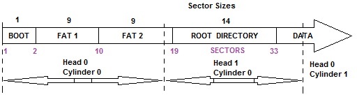
- All sectors are 512 bytes.
- The BOOT sector is always the first sector of the disk and must not be overwritten with data. It contains the disk parameters, and if bootable it will contain the booting instruction.
- There are usually 2 FAT's, which should be identical, otherwise there has been a disk error. They are both 9 sectors in size.
- The Root Directory contains all the file information about the files stored on the disk. It is 14 sectors in size and can hold up to 224 entries.
- Everything after the Root Directory is a data storage area.
Converting a Start Clusters or Allocation Clusters to a CHS
CHS is Short for Cylinder Head and Sector.
When calculating the sector position on the disk you must use the following method to get the head, cylinder and sector numbers. This example assumes the cluster address is 54.
- Ignore the BOOT sector, as it is at sector 0 for the purpose of this calculation. Add 2x9 sectors for the FAT's + 14 sectors for the Root Directory = 32.
- 54 + 32 = 86
- 86 / 18 = 4 Cylinders
- 4 * 18 = 72 sectors in the cylinders
- 86 - 72 = 14 Sectors remainder
- The number of cylinders is even, so the Head=0, odds are Head=1
- There are 2 heads so divide 4 cylinders by 2 = cylinder 2 on the disk
If you need to work is backwards from a CHS to an Allocation Cluster do this. For example using the previous convertion.
- Cylinders * 18 * Heads = 2 * 18 * 2 = 72
- Add the sectors 72 + 14 = 86
- Deduct Offset to the data area 86 - 32 = FAT block 54
Extracting Allocation Cluster Numbers
The FAT contains a 3 byte addressing system. Each set of 3 bytes points to 2 blocks in the Disk Data Area.
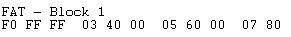
The FAT starts counting from block zero, The first 3 bytes will usually be F0 FF FF, these represent blocks 0 and 1.
F0 FF indicates if the disk needs scanning etc.., Block 1 is where the disk label would be if it had a data area.
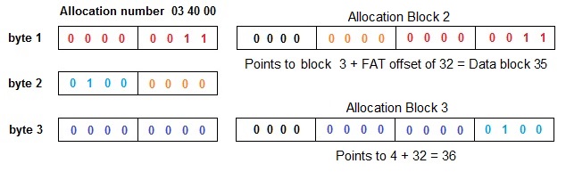
To find the correct data block number you need to manipulate the bytes as shown in the image below, using the address from the above FAT example, we get Allocation Clusers 2 and 3 which are byte values 03 40 00.
Reads a Cluster from FAT12
>The code sample following shows a method of achieving this in assembly code.
Reads Both Clusters from FAT12 Allocation block
The code sample following is an alternate method of achieving this by returning both cluster values.
Writes Clusters to a FAT12 Allocation block
The code sample following converts the clusters back into a FAT12 allocation block.
Calculate the offset to a FAT12 Cluster block
The code sample following calculates to location of a cluster / allocation block within the FAT.
Converts a Cluster Number to a Disk sector CHS
The code sample following converts a cluster number to its
CHS (Cylinder, Head, Sector) on the Disk.
Converts CHS sector to a Cluster Number
The code sample following calculates the Cluster number from the CHS (Cylinder, Head, Sector).
Last Update 24/12/2021